Installation Literature
TAG-X SMART RAIL
Warning:
- TURN OFF POWER TO THE ELECTRICAL CIRCUIT BEFORE INSTALLING OR MODIFYING WIRING.
- ALL WIRING TO BE COMPLETED PER LOCAL, STATE, AND FEDERAL CODES BY A CERTIFIED ELECTRICIAN.
- DO NOT CONNECT POWER UNTIL SMART RAIL INSTALLATION IS COMPLETE.
Installation tips:
- Cut covers up to 1/16” (1.6mm) longer to ensure a tight fit.
- Read full installation instructions before beginning.
Tools:
Safety Glasses, Tape Measure, 3/8” socket for machine screw hex bolt, 7/16” socket for wood screw hex bolt Level, Power Drill, Drill Bits - 1/4” masonry (concrete/concrete block), Power Miter Saw, 10” Blade with 60-80 Carbide Tipped Teeth, Shears, Utility Knife

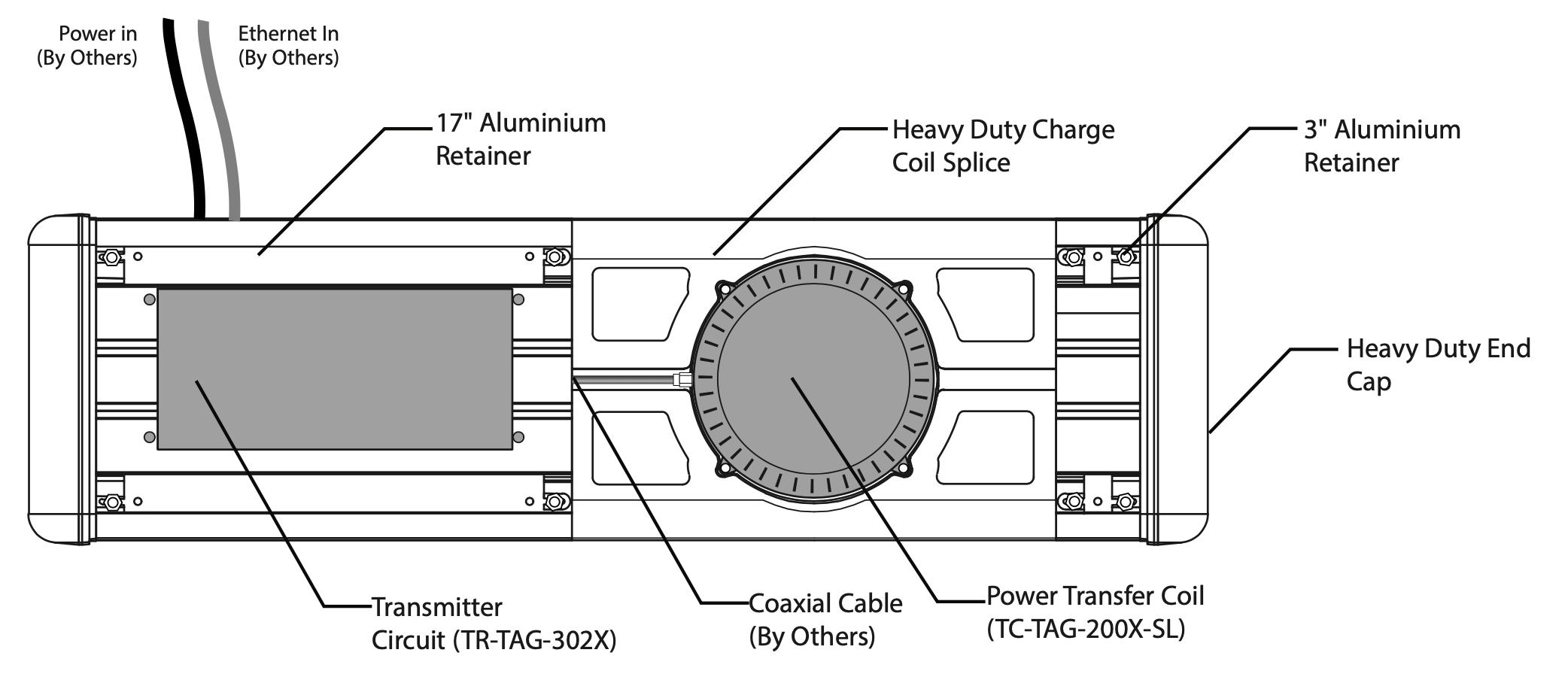
General Component Layout Diagram

Two Unit Layout Example

Detail Drawing View

Exploded View

Figure 1
- Pre-assemble 17" Aluminum retainers, Heavy Duty Charge Coils and 3" aluminum retainers. Fasten using supplied 1/4-20 x 1" hex head flange bolts and nuts. (Install so is head on back with threads pointing out within the wings of the retainer)
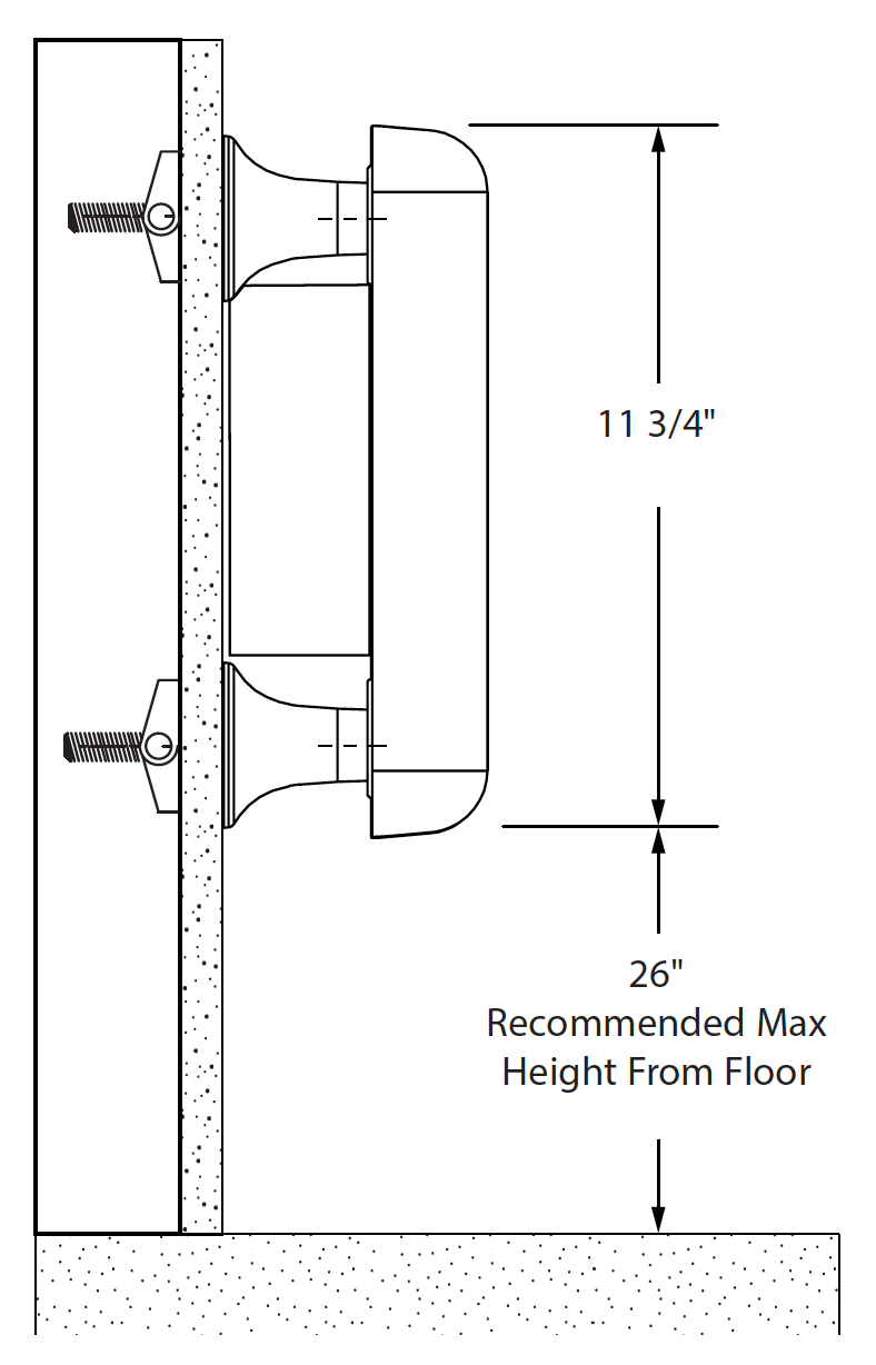
- Locate the components against the wall at the desired height (Recommended no more than 26" of finish floor per ADA requirements).
- Using the pre-drilled holes in the aluminum retain-er, mark the bracket holes on the wall.
- Remove assembly from the wall and pre-drill the holes using a 3/4" drill bit

Figure 2
- Before installation, unscrew the power switch from the Transmitter circuit. Gently lift the switch unit from the housing and rotate 180°, so that orientation matches Figure 2 / Detail drawings. (Plug side towards LEDs)
- Mount the Transmitter circuit to the 17" retainer using supplied flathead screw and nut. See Figure 2a

Figure 3
- Pre-thread mounting hardware as shown. Ensure toggle anchors are loose and able to be fully inserted into the pre-drilled holes.
- Once toggle anchors are inserted into holes, tighten fasteners to secure the rail to the wall.
- After mounting the rail, connect the power and Ethernet cables to the Transmitter circuit. (Cables by others) (Do not turn on the unit until installation is complete)

Figure 4
- Before installing the power transfer coil, attach the coaxial cable to the transmitter circuit.

Figure 5.
- Run the coaxial cable through the recessed groove in the heavy-duty charge coil splice. Attach the charge coil to the power transfer coil
- Place the power transfer coil into the recessed pocket of the heavy-duty charge coil splice. Fasten the transfer coil to the splice using the supplied plastic screws and nuts.
- Attach the end caps to both ends of the rail using the supplied 1/4-20 x 1" flanged head screw and nuts.

Figure 6.
- Covers are supplied in set lengths which will need to be trimmed based on production tolerances. When dry fitting covers, it’s critical that the machined pocket in the cover is centered over the power transmitter coil.
- When cutting vinyl, use a fine toothed finish saw blade to ensure a clean smooth cut.
- Snap the covers onto the rail, and repeat next steps for next section of rail, if applicable.
- Before applying the Tag-X label to the recessed pocket on the cover, clean the recessed surface with rubbing alcohol and a lint-free cloth.
- Remove the backer from the sticker, align a edge of the sticker with the edge of a recess, and press sticker face into pocket applying firm even pressure.
- Turn unit on, and clean work area.

